When acoustic waves are emitted into a complex solid medium like concrete, several acoustic wave modes are generated, and these different wave modes are reflected and scattered from interfaces and internal features such as backwalls/sidewalls, rebars, pipes, aggregates, voids etc. These reflections and scatterings can occur multiple times and interfere constructively or destructively. Sometimes these effects can cause very complex wave patterns propagating within the concrete which in turn can be seen as large amplitude variations, noise, and artifacts in the images. These undesired artifacts make the images more challenging to interpret, and a considerable amount of research are being performed to reduce these effects.[1]- [6]
In this article we will introduce and present some results from EI’s new signal processing approaches to reduce these artifacts and improve the images to make the results more easily interpretable. We will focus on a dynamic filtering approach to reduce artifacts generated by surface acoustic waves (SAWs) and directional filtering to improve SNR, attenuate artifacts, and reduce amplitude variations.
Surface wave suppression
One of the wave modes generated when ultrasound is emitted into concrete is compression waves, which the EI scanner is currently utilizing to image the internal features of the concrete material. Other wave modes, however, such as shear waves and surface acoustic waves are unwanted during the imaging process and will interfere with the compression waves and contaminate the signals. Of the two contaminating wave modes, surface waves are by far the most prominent, and can in some circumstances be several orders of magnitude higher in amplitude than the reflected compression waves from internal features. On the other hand, SAWs can be beneficial for other types of inspections, and are utilized by the EI scanner to estimate wave velocity and will also in a coming update be used to estimate compressive strength. Surface waves are generated to some degree by all NDT ultrasound devices and are handled and utilized by using various approaches [2][3][4].
In the images of the EI the SAW contamination, when prominent, will appear as several bands in the near surface region which can be visible from a few centimeters’ depth up to around 20 cm. The extension and severity of the SAW contamination depends on several factors, concrete quality, acoustic coupling, and material velocity. Although EI scanner already uses several techniques to reduce SAW contamination such as acoustically optimized elastomer coupling and the use of 3D SAFT algorithm, it is still insufficient in some cases. We are here using a signal processing approach that uses a locally adaptive filtering approach which among other characteristics considers the length and direction of travel of the SAWs to attenuate these, while preserving real featb
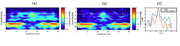
Figure 1. D-scan showing a near surface air filled duct. The left image (a) is without applying the SAW reduction filter and shows three horizontal lines which is caused by SAW contamination. The middle image (b) shows the same D-scan slice after applying the SAW reduction filter with the horizontal lines almost non-visible. The right figure (c) is a profile plot of the amplitude values along the dotted white line in (a) and (b) confirming that the algorithm provides a significantly improved SNR of several dB between the air duct and the background.
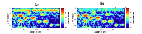
Figure 2. D-scan from a stepped block with air ducts at different depths before (a) and after (b) surface wave filtering. The image in (a) shows severe surface wave contamination in the region around 5-10 cm depth, which is significantly attenuated when applying the filter while preserving the real features, making the image look cleaner and easier to interpret.
Along- and cross-track smoothing
Concrete is a highly diverse medium with various aggregates, air pores, reinforcement density etc. These variations will cause scattering and attenuation of the signal and could result in very complex and cluttered images with fragmented features. By averaging across larger segments of the 3D image extended features will appear more continuous causing a more easily interpretable image. In addition, the amplitude of the larger objects can often be more accurate as the smaller local variations, which are often caused by properties that are not of interest, will be averaged out, and the amplitude will be based on measurements from a larger area [6]. The cost of applying this extended averaging is resolution and attenuation of smaller features.
In EI’s analysis tool there is currently introduced two directional weighted average filters, along-track, and cross-track smoothing, which allows the user to apply a stronger filtering of noise and artifacts to make the images cleaner and the features more connected, primarily when the direction of elongated features is known. The along-track smoothing is beneficial when scanning along a feature, such as following a tendon duct to monitor amplitude differences for detecting grouting defects. For the cross-track filtering a further advantage is that it will interpolate the stitched scan lines, and the inherent fall-off towards the edges of the scanning system, and remove the discontinuities between the adjacent scans, making the image appear more unified.
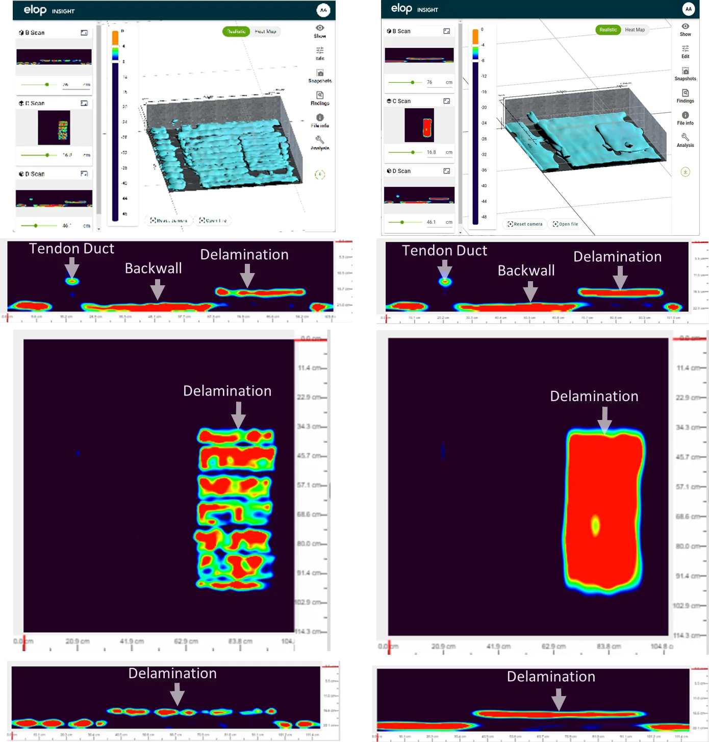
Figure 3. Images of a specimen containing a delamination and a tendon duct before (left column) and after (right column) applying the cross-directional smoothing filter. The 3D image and the B-, C-, and D-scan slices are cleaner, more easily interpretable, and the features appear more consolidated after applying the filter (the right column).
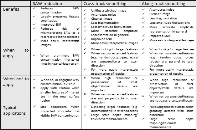
As the directional filters can remove some details they should be used with caution. Some general recommendations on when to apply and when not to apply the directional smoothing filters are suggested in the table below.
References