The implementation of SAFT in Elop Insight offers a range of benefits including high SNR and resolution, and the ability to generate easily interpretable 3D spatial images of internal features and defects in concrete structures.
Synthetic Aperture Focusing Technique (SAFT) [1][2] and its cousins SAS (Synthetic Aperture Sonar) [3][4], and SAR (Synthetic Aperture Radar) [5][6], are well-established methods to form images with spatial information from the “raw” amplitude-vs-time-data output from the sensors (what we commonly refer to as A-scans in ultrasonic testing). These methods are successfully utilized within diverse fields such as topography, oceanography, geology, and Non-Destructive Testing (NDT), and can make the data considerably easier to interpret by placing the features into a real-world spatial coordinate system, while at the same time providing improved Signal-to-Noise Ratio (SNR) and resolution.
When A-scans from all sensor element combinations in an array are utilized during the image reconstruction this is often termed Full Matrix Capture (FMC), and when these A-scans are focused into each grid position in the imaged volume this is often termed Total Focusing Method (TFM).
In Elop Insight (EI), the world’s first and only rolling ultrasonic scanner for concrete, we use an implementation of SAFT where all 8 transmitters and all 8 receivers are utilized giving up to 64 combinations as in FMC for the cross-track synthetic aperture. In addition, we are using the scanner’s built-in rotational encoder during movement to extend the captured matrix in the scan direction to acquire many more data points and create an along-track synthetic aperture.
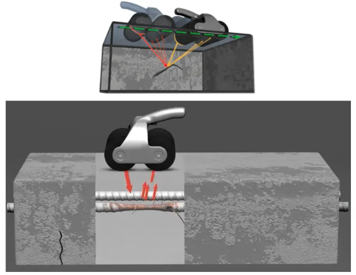
Figure (a) Illustration of the Elop Insight SAFT algorithm emitting ultrasonic signals from a transducer element on the Tx wheel and receiving the echo from a feature inside the concrete with the transducer array on the Rx wheel. The echo from the same part of the same feature is received multiple times for different Tx-Rx combinations, and as the scanner is moved along the surface.
Both the along-track and cross-track data are furthermore focused into each image grid point, i.e. each voxel (the 3D equivalent of a pixel), according to the TFM scheme, making the imaged features focused on all orientations.
To achieve the focusing for each voxel in SAFT/TFM the A-scans are delayed based on the calculated distance from the transmitter element to the voxel and back to the receiver element and the material velocity (the latter parameter can be estimated by the EI scanner). The amplitudes for the corresponding delays of all A-scans are then summed into each of the voxel positions (the algorithm is frequently also termed Delay And Sum, or DAS). An illustration of the algorithm can be seen in figure 1 along with a 3D image of a concrete sample reconstructed by the SAFT algorithm using the EI scanner. For the EI scanner typically on the order of 10 000 A-scans are used to create the amplitude data for each voxel in the 3D image in what we term high accuracy mode, which uses 2 mm along-track sampling distance (that is a full set of up to 64 A-scans are acquired for every 2 mm rolled with the scanner, which is substantially more than what can be achieved with a non-rolling device). The difference between the high accuracy and high-speed mode is primarily the along-track sampling distance and hence the number of A-scans that are summed in each voxel. In the high-speed mode, the scanner can be moved up to approximately 1 m/s (which is normal walking speed).
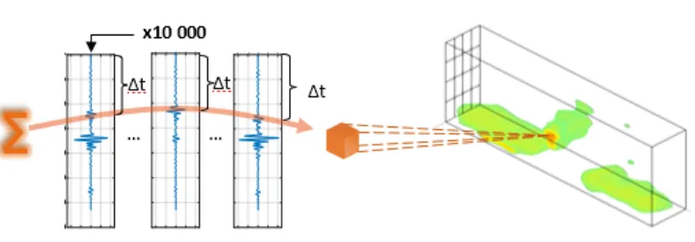
Figure (b) Illustration showing the SAFT delay and sum process where the raw A-scans from the receiver are delayed before summation according to the calculated distance from the transmitter element to the voxel and back to the receiver element and the (estimated) material velocity. For EI scanner each voxel amplitude is typically updated on the order of 10 000 times. This results in a high SNR, high resolution 3D image as shown to the right.
The advantages of the SAFT/TFM algorithm as implemented in the EI scanner are several:
- Improved SNR due to thousands of data points being averaged in each image grid point (each voxel).
- Improved resolution due to a larger synthetic aperture.
- Less sensitivity to surface roughness as a few A-scans with poor coupling would have little impact when each of the voxel amplitudes is based on thousands of other acquisition points.
- Compared to Phased Array Ultrasound Testing (PAUT) systems, the entire image is focused rather than just a narrow region which is in virtually all practical applications the case for PAUT.
- Much faster compared to PAUT systems if they have a similarly wide range resolution as the focusing, or synthetic beamforming is done on the receiving side rather than physical beamforming.
- Several wave modes are generated when acoustic waves are transferred into a solid material like concrete, including pressure waves, shear waves, and surface waves. The pressure wave echoes are what EI uses to generate the images, while the other wave modes cause contamination of the signals. However, since these undesired wave modes travel at a substantially different speed than pressure waves they are defocused by the SAFT algorithm, while the wanted pressure waves are focused, causing significantly improved SNR.
- Along- and cross-track synthetic aperture normally makes it sufficient to scan an area in one direction (no need to cover the area twice with perpendicular scans as is generally the case with Ground Penetrating Radar (GPR) and other directional scanners).
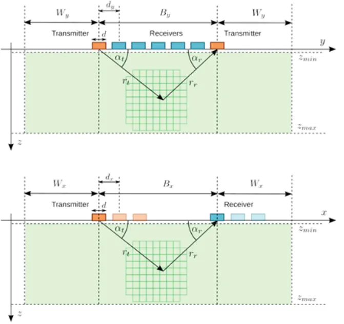
Figure (c) and (d) Further details of the SAFT geometry for the cross- and along-track imaging – respectively.
The implementation of SAFT in Elop Insight offers a range of benefits, including high SNR and resolution, and the ability to generate easily interpretable 3D spatial images of internal features and defects in concrete structures. With its high-speed scanning capabilities (up to 4km/h), the scanner provides fast and accurate results, contributing to a safer and more efficient approach to concrete inspection. This makes Elop Insight an ideal solution for construction and NDT industry.
References
[1] D. H. Johnson and D. E. Dudgeon. Array Signal Processing: Concepts and Techniques. Signal processing series. Prentice Hall, Englewood Cliffs, NJ, USA, 1993.
[2] M. Soumekh. Fourier Array Imaging. Prentice Hall, Englewood Cliffs, NJ, USA, 1994.
[3] W. G. Carrara, R. S. Goodman, and R. M. Majewski. Spotlight Synthetic Aperture Radar: Signal Processing Algorithms. Artech House, Norwood, MA, USA, 1995.
[4] D. Massonnet and J. Souyris. Imaging with synthetic aperture radar. EFPL Press, 2008. ISBN 0849382394.
[5] R. E. Hansen. Introduction to Synthetic Aperture Sonar. In N. Z. Kolev, editor, Sonar Systems, chapter 1, pages 3–28. Intech, September 2011. ISBN 978-953-307-345-3. URL
[6] M. P. Hayes and P. T. Gough. Synthetic Aperture Sonar: A Review of Current Status. 34(3): 207–224, July 2009.